RC ~ RC with Ardupilot
MAVLink defines certain message types one of which is "RC_CHANNELS_OVERRIDE" message. These messages are used to command the Flight Controller (FC) to ignore all inputs from the regular RC-Receiver (SBUS, SUMD, CPPM, etc) and instead override the RC channels with the information that is sent as a payload with the MAVLink RC_CHANNELS_OVERRIDE messages. Thus this feature can be used to override the RC Transmitter and control the UAV from a GCS but it can also be used as the sole way to fly the drone. There is no need to have a standard RC receiver connected to the FC.
- Currently limited to 8Ch (due to legacy MAVLink v1 support only)
- review the RC General Page in the wiki
-
Duplicate the currently used Model in your Taranis and assign a new name (e.g.: "MyQuad" -> "MyQuad EZ-WBC")
-
Switch to the new Model "MyQuad EZ-WBC"
-
Enter the "MODEL SETUP" Screen and turn "
Internal RF Mode=OFF" and "External RF Mode=OFF".This deactivates the internal and external RF module to not cause any HF-interference. For an external module it is good practice to even remove it physically from the radio. (Some HF-modules do not respect the "OFF"-Setting and will transmit HF anyway)
-
Edit the wifibroadcast-1.txt in the boot partition (both AirPi & GroundPi) and set:
TELEMETRY_TRANSMISSION=wbcTELEMETRY_UPLINK=mavlinkRC=mavlinkCTS_PROTECTION=Y -
Unplug your regular RC-Receiver from PixHawk and(!) cut power
-
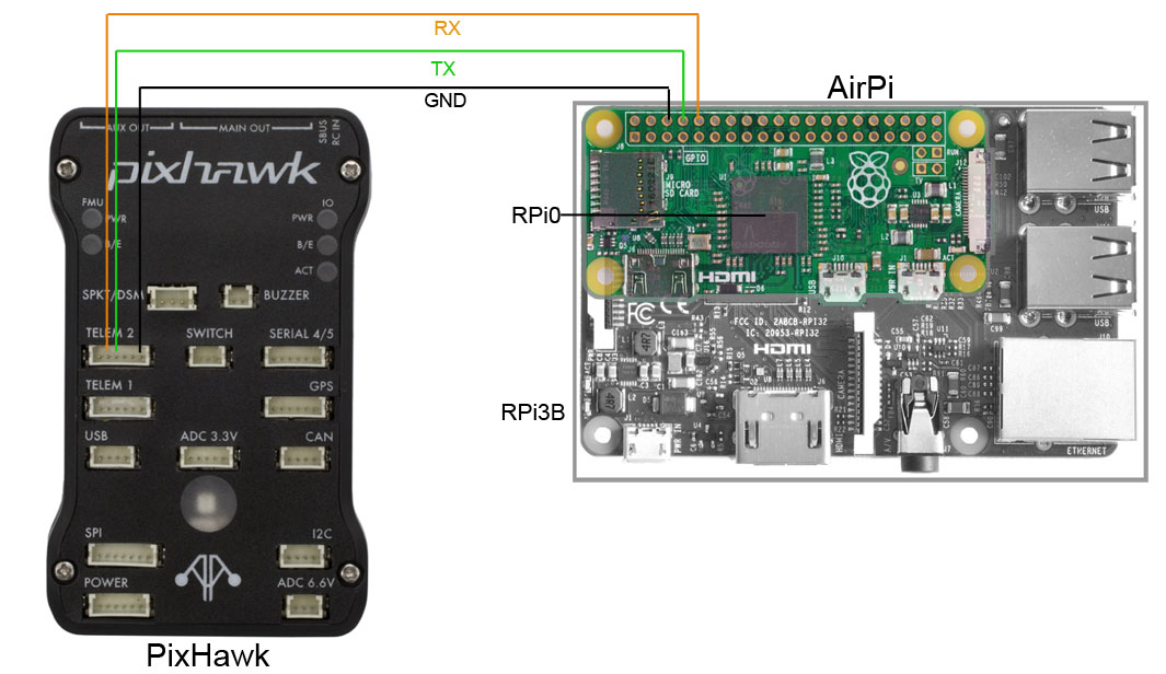
Connect your AirPi serial to Telem1 of your PixHawk (you may also use Telem2, following settings need to modified accordingly)
-
Connect to your PixHawk via Mission Planner (USB) and open the Full-Parameter-Tree. Configure the following Parameters as decrsibed here
-
Save the parameters and power off your Pixhawk (also cut USB connection to PC as it powers your PixHawk as well)
-
Now power everything up again: Pixhawk + AirPi and your GroundPi
-
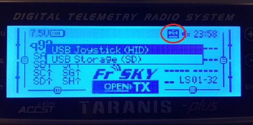
Once up and running connect your Taranis via USB to the GroundPi
You will notice a small "USB icon" showing on the Taranis Display. It is now in USB-Joystick Mode / Depending on your OpenTX version it might even prompt you to choose the mode
-
Connect your PixHawk via USB to PC and connect via Mission Planner
-
Go the the RC-Calibration dialog and happily see the RC Channels moving :-)
-
Perform the RC-Calibration
-
Check Failsafe Settings
Arm ArduCopter - remove Props first!! - and throttle up. This is essential since FailSafe won't kick-in when not in flight. Test both scenarios:
-
Unplug USB-JoyStick --> FailSafe should be initiated
-
Power-Off GroundPi --> FailSafe should be initiated
-
The Pixhawk Flight controller has 2 serial ports dedicated to telemetry
-
Telem1(aka Serial1) is for MAVLink communication with flow control support. (high power port up to 1A) -
Telem2(aka Serial2) is for MAVLink communication with flow control support.
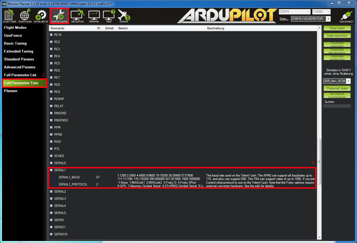
The telemetry ports can be configured through Mission Planner (GCS) by setting the parameters listed below.
Open the Config/Tuning | Full Parameter Tree page.
Set the baudrate of the respective telemetry port to 57600 baud. For telemetry ports used for MAVLink communication you may select to use MAVLink1 by setting the SERIALx_PROTOCOL to “1” or MAVLink2 by setting SERIALx_PROTOCOL to “2”.
Set:
SERIAL1_BAUD=57
SERIAL1_PROTOCOL=1 (for EZ-WifiBroacast >= v1.6 final choose =2 for MAVlink 2)
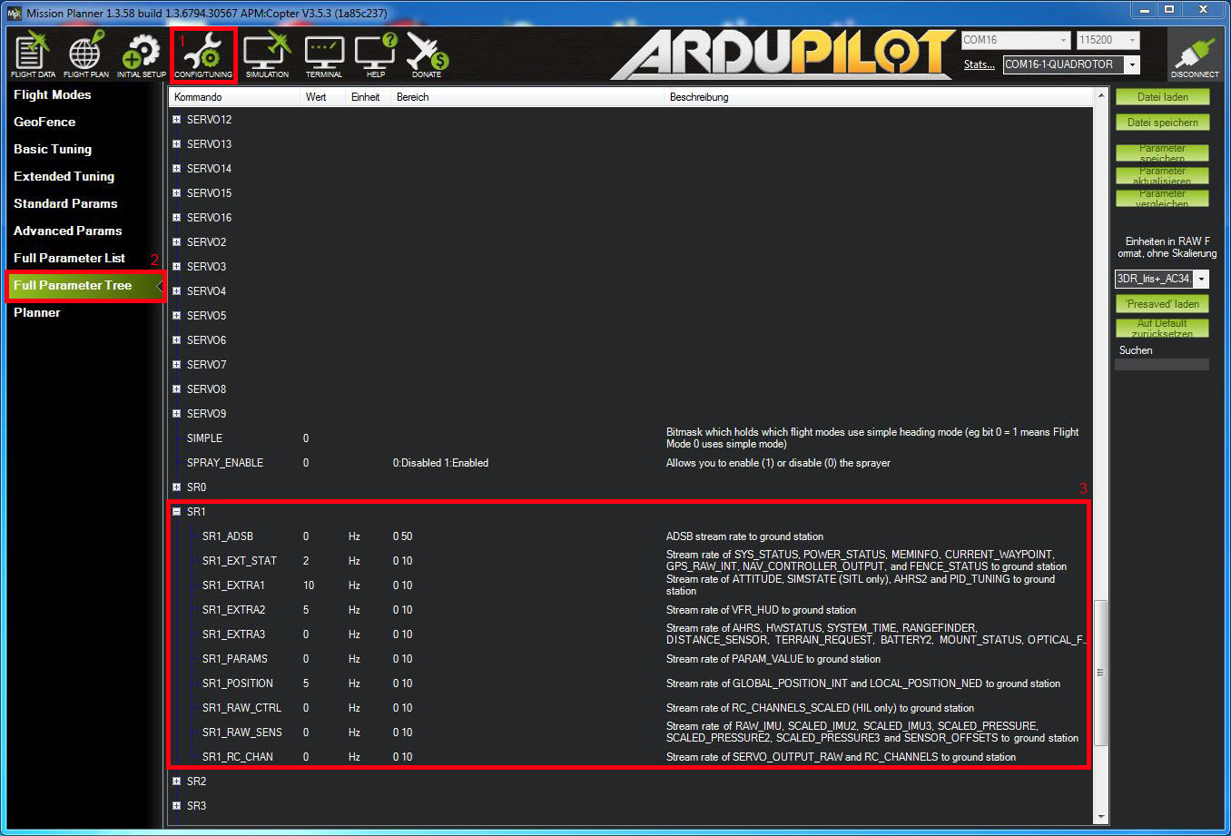
Arducopter supports so called "telemetry streaming". You can choose from different subsets of telemetry information and how often you want the Flight Controller (FC) to stream that particular set of data per second (defined in Hz). These parameters are the so called SRx_Parameters where x represents the serial port number. In this walk-through we are using Telem1 (aka Serial1) - hence X=1.
In order not to transmit telemetry data too often over our radio link, we have to select just the necessary data (the right subsets of information) and at the same time find a good compromise on how often this data should be send and thus be updated. The following parameters have to be found working very reliably:
SR1_ADSB=5
SR1_EXT_STAT=2
SR1_EXTRA1=4
SR1_EXTRA2=4
SR1_EXTRA3=2
SR1_PARAMS=10
SR1_POSITION=2
SR1_RAW_CTRL=0
SR1_RAW_SENS=2
SR1_RC_CHAN=2
Now we are finished. After saving the parameters to the FC (Save Parameters Button), power cycle your FC and you should see all your OSD elements happily populated with the correct telemetry informations.
Note: If you want to learn more specific details about SRx_Parameters consult this comprehensive MAVlink documentation at ardupilot.org.