-
Notifications
You must be signed in to change notification settings - Fork 3
_SKU_TEL0125_FireBeetle_Covers LoRa_Radio_868MHz
Angelo edited this page Dec 30, 2019
·
1 revision
DFRobot FireBeetle萤火虫系列是专为物联网设计的低功耗微控制器。此款FireBeetle LoRa 868MHz无线传输模块,采用高性能SX127x LoRa 868MHz芯片,内置PA增益,在空旷可视范围内可达5KM,实测城市距离大于1KM。支持FSK调制方式,支持最大传输速率300Kbps,支持LoRaTM,最大传输速率37.5Kbps。支持Arduino,支持低功耗,在睡眠模式下电流小于0.2uA。可以应用在远程抄表、家庭自动化检测、轮胎气压监测、健康监测、可穿戴等系统。
注意事项:在同一网络中,模块的无线信号参数都应设置为相同参数,避免因模块之间信号参数不一致导致不能通信。
- 工作电压:3.3V
- 工作频段:868MHz
- 调制方式:LoRa 扩频
- 输出功率:≤20dBm
- 接收灵敏度:-139dBm
- 发射电流:≤120mA
- 接收电流:≤15mA
- 休眠电流:≤1uA
- 发送模式电流:120mA(RFOP=+20dBm) - 20mA(RFOP=+7dBm)
- 发射功率范围:-1dBm~20dBm(Max)
- FIFO/直接模式两种传输模式
- 工作频率:800MHz~900MHz(典型值968MHz)
- 传输距离:5Km(可视距离)
- 数据传输速率:@FSK,1.2~300Kbps @LoRaTM,0.018~37.5Kbps
- 调制方式:LoRaTM、FSK、GFSK、OOK
- 内置天线静电保护
- 127分贝动态范围RSSI
- 256字节FIFO与CRC跳频功能
- SPI接口
- 5个软件控制GPIO(可用作中断)
- 工作温度:-20℃~+70℃
- 产品尺寸:58 x 29 mm
- 安装孔位置:53 x 24 mm
- 安装孔尺寸:内径3.1mm
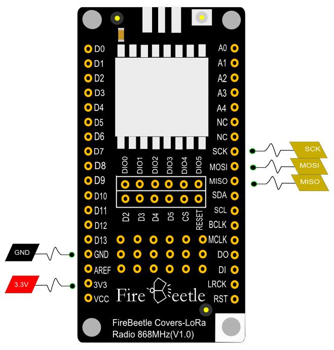
FireBeetle Covers-LoRa Radio 868MHz主要通过SPI接口(MISO, MOSI, SCK, CS, RESET)通信,并将这些控制端口引到FireBeetle主板的SPI接口上(MISO,MOSI,SCK)上,片选CS和RESET通过杜邦线与D2、D3、D4、D5连接。
 |
|
| 注:NC不连接,VCC为电源电压输出(5V-USB 供电时为5V, 3.7V-锂电池供电时为电池电压) |
-
硬件
- 2 x ESP32控制板
- 2 x FireBeetle Covers-LoRa Radio 868MHz模块
- 连接线
将CS连接到D4,RESET连接到D2,库文件默认连接方式,当然你也可以修改程序连接到其他IO口(通过init函数传递参数:init(uint8_t NSSPin = NSS_PIN, uint8_t NRESETPin = RESET_PIN))。
-
软件
- Arduino IDE, 点击下载Arduino IDE
- 直接将ESP32控制板和LoRa模块拼合
- 将ESP32控制板通过USB连接到PC
[https://github.com/DFRobot/DFRobot_Lora请先下载FireBeetle Covers-LoRa Radio 868MHz库] 如何安装库文件,点击链接
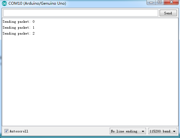
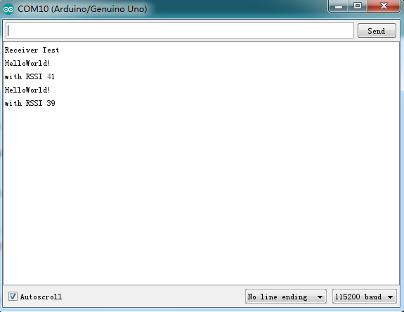
- 将主从程序分别下载到两块ESP32控制板上
- 从模块(Slave)代码程序
|
/*!
 * @file receiverTest.ino
 * @brief DFRobot's received data
 * @n [Get the module here] http://wiki.dfrobot.com.cn/index.php?title=(SKU:TEL0125)FireBeetle_Covers-LoRa_Radio_868MHz
 * @n This example is receive.
 * @n [Connection and Diagram]
 *
 * @copyright   [DFRobot](http://www.dfrobot.com), 2016
 * @copyright   GNU Lesser General Public License
 *
 * @author [yangyang]
 * @version  V1.0
 * @date  2017-04-10
 */

#include <DFRobot_LoRa.h>

DFRobot_LoRa lora;

#define RX_LEN    11

uint8_t len;
uint8_t rxBuf[RX_LEN];

uint16_t    sendCounter = 0;
uint16_t    recvCounter = 0;

void setup()
{
  Serial.begin(115200);
  Serial.println();

  pinMode(LED_BUILTIN, OUTPUT);
  Serial.println("Receiver Test");

  while(!lora.init()) {
    Serial.println("Starting LoRa failed!");
    delay(2000);
  }
  lora.setPayloadLength(RX_LEN);  // max len is 254
  //lora.setFrequency(433000000);  // for 433mhz module
  lora.rxInit();
}

void loop()
{
  if(lora.waitIrq()) {   // wait for RXDONE interrupt
    lora.clearIRQFlags();
    len = lora.receivePackage(rxBuf);  // receive data
    Serial.write(rxBuf, len);
    Serial.println();
    lora.rxInit();    // wait for packet from master

    // print RSSI of packet
    Serial.print("with RSSI ");
    Serial.println(lora.readRSSI());
    Serial.print("recvCounter ");
    Serial.println(recvCounter ++);
    static uint8_t i;
    i = ~i;
    digitalWrite(LED_BUILTIN, i);
  }
}
|}
- 主模块(Master)代码程序
|
/*!
 * @file sendTest.ino
 * @brief DFRobot's send data
 * @n [Get the module here]
 * @n This example is send.
 * @n [Connection and Diagram]
 *
 * @copyright   [DFRobot](http://www.dfrobot.com), 2016
 * @copyright   GNU Lesser General Public License
 *
 * @author [yangyang]
 * @version  V1.0
 * @date  2017-04-10
 */

#include <DFRobot_LoRa.h>

DFRobot_LoRa lora;

uint16_t sendCounter = 0;
uint8_t sendBuf[] = "HelloWorld!";

/* The default pin:
 *      SS:D4
 *      RST:D2 (If you are using the FireBeetle Board-ESP8266 motherboard controller, the RST defaults to D3)
 */

void setup()
{
  Serial.begin(115200);
  Serial.println();
  pinMode(LED_BUILTIN, OUTPUT);
  digitalWrite(LED_BUILTIN, LOW);

  while(!lora.init()) {
    Serial.println("Starting LoRa failed!");
    delay(2000);
  }
  //lora.setFrequency(433000000);  // for 433mhz module
  Serial.println("LoRa begin successed");
}

void loop()
{
  static int blink;
  Serial.print("Sending packet: ");
  Serial.println(sendCounter);
  digitalWrite(LED_BUILTIN, blink);
  blink = ~blink;

  // send packet
  lora.sendPackage(sendBuf, sizeof(sendBuf)); // sending data, max len is 254
  lora.idle();    // turn to standby mode

  sendCounter++;
#if 0
if(counter%10 == 0) {
  lora.sleep();
  delay (5000);// sleep 5 seconds
}
#endif

  delay(2000);
}
|}
- pin脚间距:2.54mm
- 安装孔间距:24mm/53mm
- 安装孔尺寸:3.1mm
- 主板尺寸:29.00mm×58.00mm
- 板厚:1.6mm
还没有客户对此产品有任何问题,欢迎通过qq或者论坛联系我们!
| 更多问题及有趣的应用,可以 访问论坛 进行查阅或发帖。 |


