Shader filter
In this wiki you will learn how to create a shader inside Olive video editor and how to integrate it with the node system. Shaders are based on GLSL language and allow to create video effects or transitions that are not built-in in Olive.
The GLSL shading language is a C-style language for composing and elaborating images and videos. If you are new to GLSL language, please visit: https://www.khronos.org/opengl/wiki/OpenGL_Shading_Language and https://en.wikipedia.org/wiki/OpenGL_Shading_Language.
Note: this wiki will be applicable when PR 1839 is merged.
When this happens, (or if you want to clone the relevant branch of the project), you can download a demo project with the .ove file and the relevant footage to try out what this wiki explains. The result you should obtain is this. This demo implements most of the filters present in Olive 0.1, ported to OpenGL 3.2. You can also download this project that is focused on transition, whose result is this video
This wiki assumes that you have a basic knowledge of Olive node editing workflow.
Olive provides two nodes that allows you to implement a GLSL script. The first can be found under "Filter" nodes and is thought to be applied to an input texture to create a custom effect. The second can be found under the "Transition" button of the toolbox and is used as a transition (drag and drop across two adjacent strips). This will allow you to create custom transitions.
Let's start with an example. Let's:
- open Olive and create a new sequence
- import some footage (a video or a still image)
- drag the footage on the timeline and click over the generated clip
- go the node editor
Inside the node editor, right click and select, from context menu: Filter > Shader.
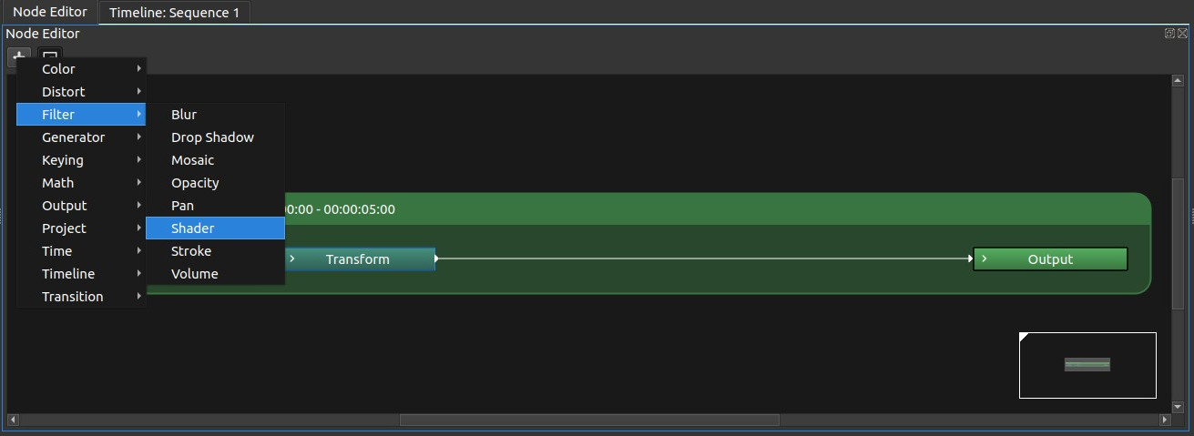
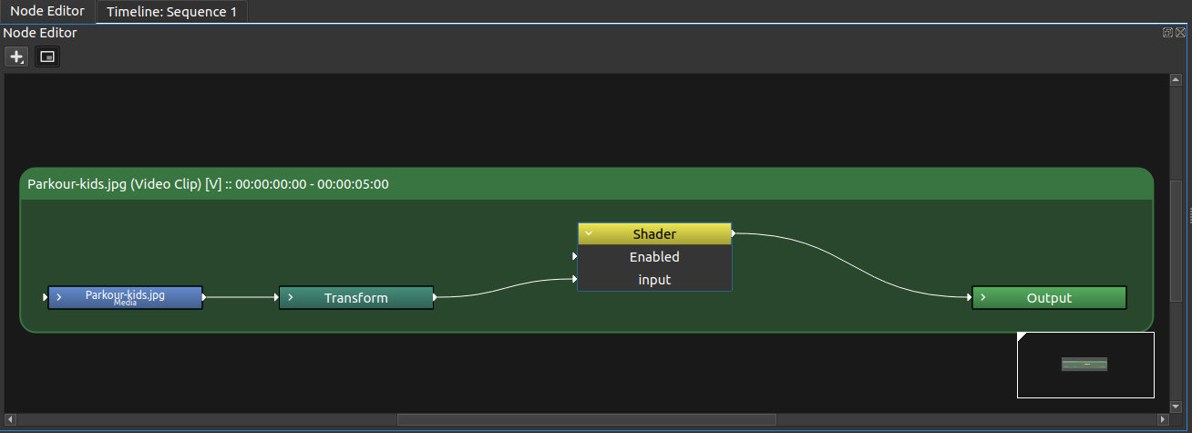
A new node will show with two connectable inputs: the enable input is common to all nodes, while input can be connected to an image or vide clip, or to the output of another node. This two inputs are always present and do not depend on GLSL code that will be written by the user.
Let's connect the output of transform node to the input of the shader node, and the output of the shader node to the output node. We will see the image as is.
If you watch the node parameters pane, you will see two non-connectable inputs. The are named Shader code and Issues: both are text field that can be edited by clicking the 'edit' button on the right, (the one with a beam icon). Both can not be edited from text area shown in Video Nodes pane.
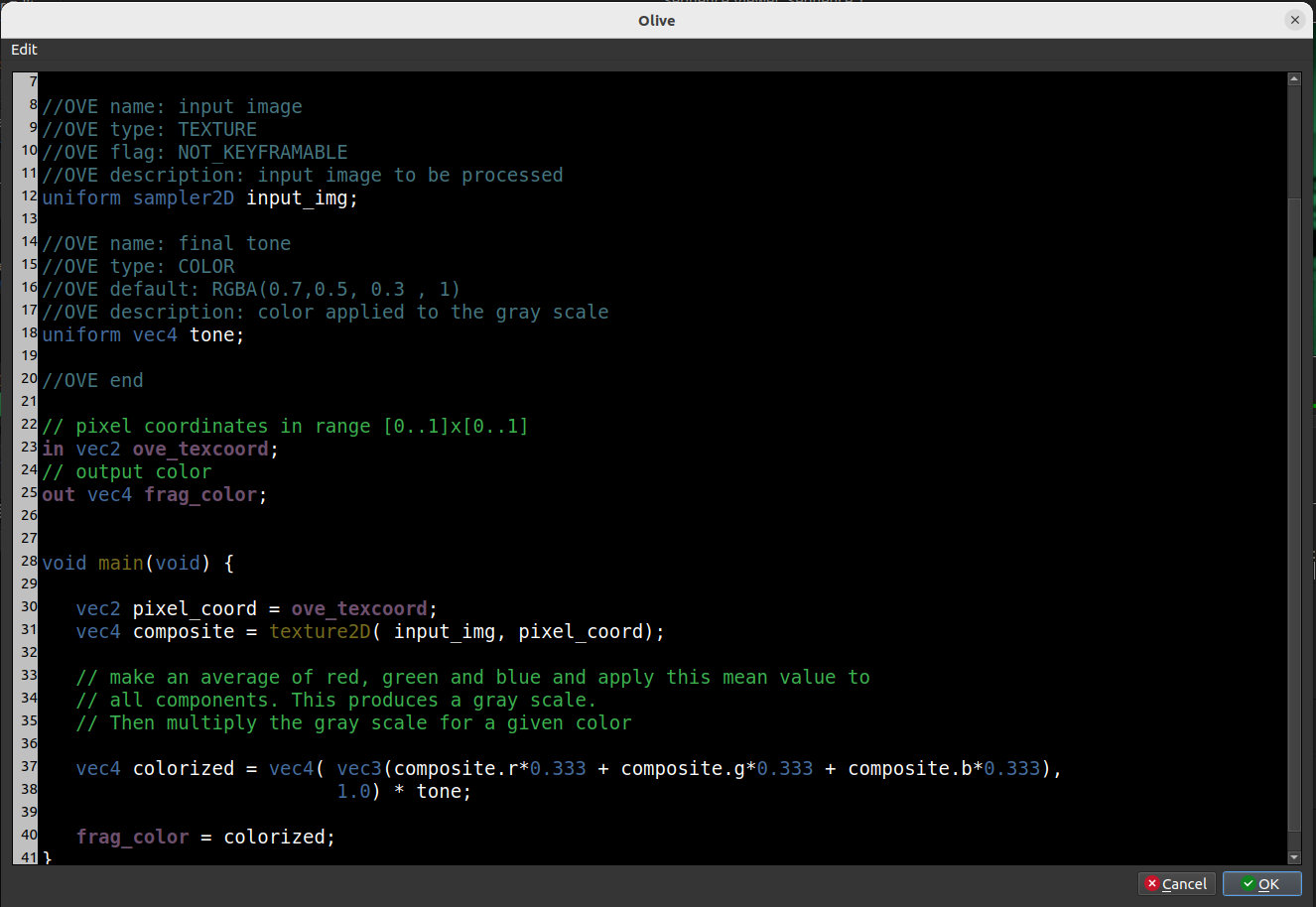
Next, click the 'edit' button of Shader code; a code editor will show.
Now, just trust me and paste the following code. We will dig it later.
//OVE shader_name: colorize
//OVE shader_description: This script takes an image as input and desaturates it
//OVE shader_description: into a gray-scale image.
//OVE shader_version: 1.0

//OVE main_input_name: My Input
uniform sampler2D tex_in;

//OVE name: final tone
//OVE type: COLOR
//OVE default: RGBA(0.7,0.5, 0.3 , 1)
//OVE description: color applied to the gray scale
uniform vec4 tone;

//OVE end

// pixel coordinates in range [0..1]x[0..1]
in vec2 ove_texcoord;
// output color
out vec4 frag_color;


void main(void) {

   vec2 pixel_coord = ove_texcoord;
   vec4 composite = texture2D( tex_in, pixel_coord);

   // make an average of red, green and blue and apply this mean value to
   // all components. This produces a gray scale.
   // Then multiply the gray scale for a given color

   vec4 colorized = vec4( vec3(composite.r*0.333 + composite.g*0.333 + composite.b*0.333),
                          1.0) * tone;

   frag_color = colorized;
}
Click “OK” button, so the code editor hides.
When the editor is closed, the code is parsed. The node has now the label “colorize” and in Issues we read "None". This means two things: the metadata for the inputs are valid and the shader can be compiled.
We have a new input, final tone, that is a color that can be set by the color picker dialog.
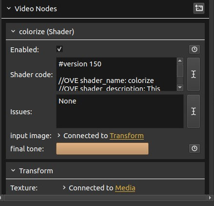
Let's keep the default final tone. The result is:

We have created a filter that colorizes a video. It can be used to make a Black & White effect or the so called "sepia" tone. The final tone input can be key-framed so that it changes over time.

Let’s take a step back and try to understand what we have done.
The purpose of the whole script is to give a value to the frag_color variable: this will become the output of the node. The script operates on red, green and blue,(r,g,b), components of the input image and assigns a mean value to each of them; this de-saturates the input image. After that, the result is multiplied by the color selected by the user in the node parameter pane.
If we look at the source code in editor, we can see that commented lines can have two different colors. Regular comments are in light green; Olive special comments are in bluish green. Olive comments all start with //OVE , but it is not enough to start with //OVE to be highlighted as Olive comments.
Olive comments are the ones where OVE tag is followed by one of the following keywords:
- shader_name:
- shader_description:
- shader_version:
- main_input_name:
- name:
- type:
- flag:
- values:
- description:
- min:
- max:
- default:
- end:
(note the colon at the end of the keyword).
The first three keywords refer to the whole shader:
- shader_name is the name of the filter that the shader implements; this will become the label of the node in the project.
- shader_description is a description of what the filter does. Currently, this is not used by the application but may be useful if the code is shared.
- shader_version can be used if the shader code evolves, but currently is not used by the application.
main_input_name: refers to the uniform tex_in that must always be present. This is a texture input that, for an implementation reason, must always be connected, otherwise Olive will not compute the node shader code.
The default human name in UI for this uniform is Input, but you can use this OVE comment to give it a different name. If this comment appears more than once, only the last occurrence will be used.
WARNING: even if you write a shader that does not require a texture, remember to connect this input to something, (for example a dummy "Solid" node).
WARNING: if you use many shaders in your project, remember to give them different "shader_name"s if they have different code. Otherwise Olive may use the last shader that has been compiled for all shader nodes with the same name.
The other keywords are used to set the attributes of a uniform, i.e. a variable that will be exported as an input in the GUI. If you want to know what exactly an uniform is, please see: https://www.khronos.org/opengl/wiki/Uniform_(GLSL) .
Each tag defines an attribute of the uniform that is defined below; when the declaration of a uniform is found, these attributes are applied to it and, after that, they are cleared.
- name is the “human name” of the input, i.e. the name that the GUI will show in node parameter view. Currently, it is not possible to translate this name in a local language.
-
type defines the type of input. It’s value must be one of the following:
- TEXTURE: an image, a video or the output of another node
- COLOR: a color that can be selected with the color-select widget
- FLOAT: a floating point value that becomes a spin box in GUI
- INTEGER: an integral value that becomes a spin box in GUI
- BOOLEAN: a true/false value that becomes a checkbox in GUI
- SELECTION: an
intuniform that becomes a combo in GUI. You can specify the entries as a list of strings - POINT: a pair of numbers that represent the coordinates of a pixel normalized by the resolution. In GUI, this becomes a pair of spin boxes.
Attribute type should be declared before the ones that are described below because some other attributes, such as minimum, maximum and default, require this information in order to be converted into a value.
-
flag specifies some features of the input. Values can be:
- ARRAY means that the input is actually a set of inputs
- NOT_CONNECTABLE means that the input can be set in the parameter view pane, but it is not an input of the node in the node editor. Using this flag makes your node more usable and keeps the node editor interface neat.
- NOT_KEYFRAMABLE means that the value of this input can’t change over time
- HIDDEN means that the input is not shown either in node editor or in parameter view pane
If several flags are present, they must be in the same line separated by a space or comma.
- values is used to specify the entries of a selection combo box. These are enclosed in double quotes and can be separated by spaces or comma
- description is a brief description of the input. Olive does not use this attribute
- min is the minimum value. Applicable for FLOAT or INTEGER types
- max is the maximum value. Applicable for FLOAT or INTEGER types
-
default is the default value. Applicable for FLOAT, INTEGER and:
- for COLOR, the value must be written in the form
RGBA(*r*,*g*,*b*,*a*), where r, g, b and a are red, green, blue and alpha components in range 0.0 to 1.0; - for SELECTION, the value must be an integer between 0 and the number of entries of the selection minus 1;
- for POINT, the value must be written in the for
(*x*,*y*)where x and y are float values. If these values are between 0 and 1, the point is inside the visible frame, but a point may be outside the visible frame as well;
- for COLOR, the value must be written in the form
There is a final keyword: end. When a line that begins with //OVE end is found, the parser stops reading the code to find inputs. This can save some time in large scripts where all the inputs are at the begin.
The type of the uniform must be consistent with the type declared in metadata, according to this table:
| TEXTURE | sampler2D |
| COLOR | vec4 |
| FLOAT | float |
| INTEGER | int |
| BOOLEAN | bool |
| SELECTION | int |
| POINT | vec2 |
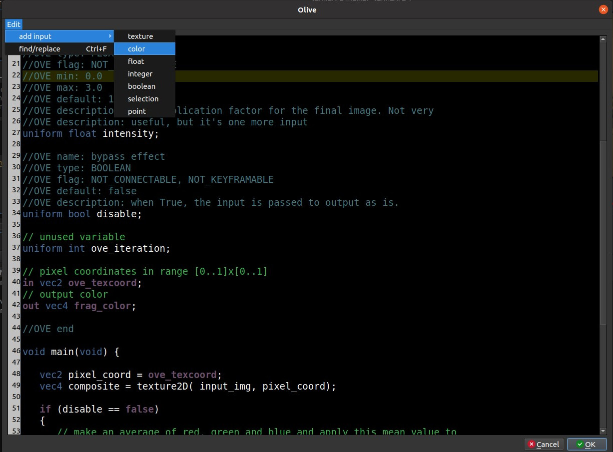
When you want to add a new input, you may use a code snippet provided by the editor menu. As the following picture shows, from menu 'Edit'>'Add input', you can add a snippet with all the attributes supported by a given type of input.
Let’s add two new inputs to our shader. They will not really make our filter more useful, but they will show two kinds of input. We will add a floating value in range 0 to 3 to increase or decrease the luma of the final image and a boolean flag to bypass the effect: when checked, the input is passed to the output as is. This is similar to the built-in Enabled input, but we will add it anyway to show this kind of input. (We'll see later how to integrate the built-in Enabled input).
Click on the beam icon again and replace the code with the following:
//OVE shader_name: colorize
//OVE shader_description: This script takes an image as input and desaturates it
//OVE shader_description: into a gray-scale image. Then a color is applied to the
//OVE shader_description: gray scale.
//OVE shader_version: 1.1
//OVE main_input_name: My Input
uniform sampler2D tex_in;
//OVE name: final tone
//OVE type: COLOR
//OVE default: RGBA( 0.5,0.4 ,0.1, 1)
//OVE description: color applied to the grayscale
uniform vec4 tone;
//OVE name: intensity
//OVE type: FLOAT
//OVE flag: NOT_CONNECTABLE
//OVE min: 0.0
//OVE max: 3.0
//OVE default: 1.0
//OVE description: a multiplication factor for the final image. Not very
//OVE description: useful, but it's one more input
uniform float intensity;
//OVE name: bypass effect
//OVE type: BOOLEAN
//OVE flag: NOT_CONNECTABLE
//OVE default: false
//OVE description: when True, the input is passed to output as is.
uniform bool disable;
//OVE end
// pixel coordinates in range [0..1]x[0..1]
in vec2 ove_texcoord;
// output color
out vec4 frag_color;
void main(void) {
vec2 pixel_coord = ove_texcoord;
vec4 composite = texture2D( tex_in, pixel_coord);
if (disable == false)
{
// make an average of red, green and blue and apply this mean value to
// all components. This produces a gray scale.
// Then multiply the gray scale for a given color
vec4 colorized = vec4( vec3( composite.r*0.333 + composite.g*0.333 + composite.b*0.333),
1.0) * tone;
colorized *= intensity;
frag_color = colorized;
}
else
{
// just pass the input, as is
frag_color = composite;
}
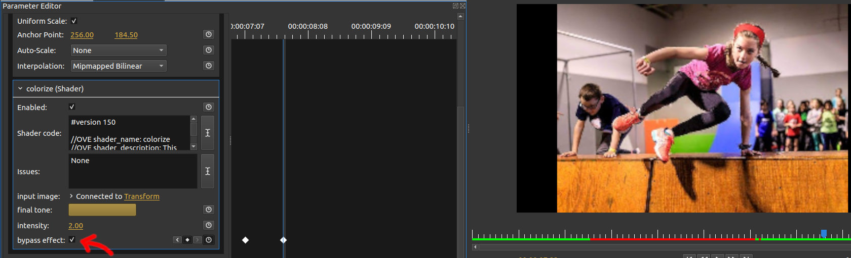
}As you can see, the GUI is updated as soon as the editor is closed with the controls for the new inputs. When any of the inputs is changed, the cache is invalidated and the output is produced.
For some shaders, you may need the resolution of your composition in pixels. This value is available by typing:
uniform vec2 resolution_in;
Note, however, that variable ove_texcoord holds the coordinate of each pixel normalized in range 0-1 both horizontally and vertically.
You will usually need such vale if aspect ratio is needed.
Sometimes you may need the current time since the begin of the sequence. In this case, just define an input of type float, (name it 'time' or give it any other name), and connect the Time node provided in Olive.
Often this value is used as a seed for random numbers: this is the case of the 'Noise' filter in the demo project.
Suppose you mistype the type FLOAT with “FLOA”. This is an invalid type, so the code parser cannot detect if minimum, maximum and default attributes are applicable. Not happy with that, suppose we also forget the semicolon after the declaration of intensity.
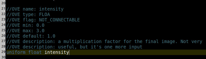
When you close the editor, the input Issues shows several messages. Clicking the beam button you can visualize them better:
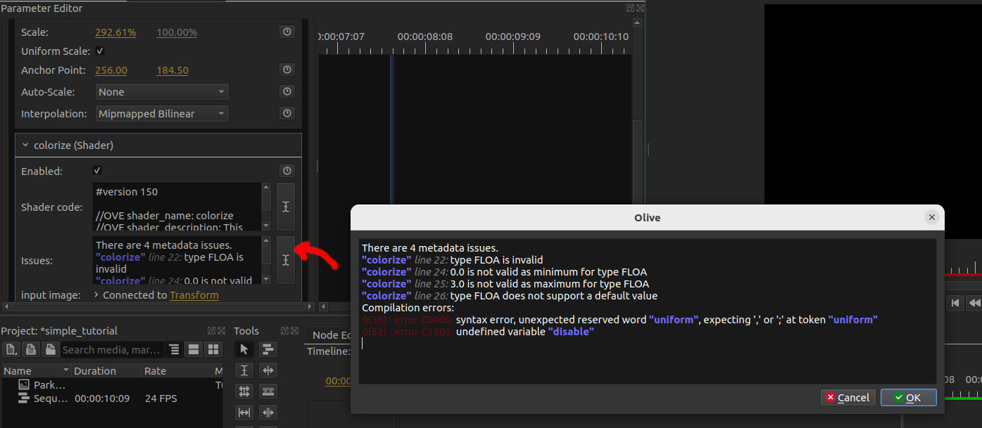
As you can see, metadata issues are separated from shader compilation issues. In metadata section, you are warned that the type of input is invalid and, as a consequence, “min”, “max” and “default” attributes loose sense. For each error, the line number is shown.
If we only has metadata errors, (but not shader errors), Olive would still produce the output and export the inputs that are legal.
Then come the errors related to shader code. In this case, it makes the difference to start the script with #version 150. In fact, if the script does not start with #version, tag #version 150 is silently added and the error messages have a line number that is wrong by one. This is why it is adviced to start with such tag. You can use any version from 100 on, but notice that most Olive filters assume you have GLSL at least version 1.50 (OpenGL 3.2).
WARNING: the tag #version must be the begin of the script, without comments and blanks before.
As the filter that you’ve just created is very cool, I expect you to feel the urge to:
- save it, so you can reuse it in other projects
- share it with all other Olive users, so that anyone can use it for free and thus make Olive more featureful
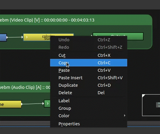
One possible way would be to save the shader code as a text file, but the users of your filter will likely be video makers and not GLSL programmers, so they don’t want to deal with code. A better way is to copy the full node. If you click on your Shader node from the node editor and hit CTRL+C, (or “copy” from menu), you have copied the node as an XML fragments, that you can paste in a text editor.
Just for reference, this is the result (in linked file):
The same node can be pasted in the node editor in another project to create a clone of the original node. This XML text holds the shader code as one of its XML tags. You can save this in a file, or send it by email or post it on a forum. You may also upload it in the official Olive filters database, where users can search (by name or by description) if someone has implemented a filter that they need, but unfortunately such database does not exist.
You may have noticed that the built-in shader editor is not a full fledged code editor. It has syntax highlight, find/replace utility, code snippets but nothing more. Hopefully the capabilities of the internal editor will grow over time, but until that day you may find useful to use a different editor for editing your shaders.
Let's go to menu Tools > preferences and open the Text Editor tab. On top of page there is a selection box where you can choose to use internal or external editor. You can modify the settings for the editor that you have selected.
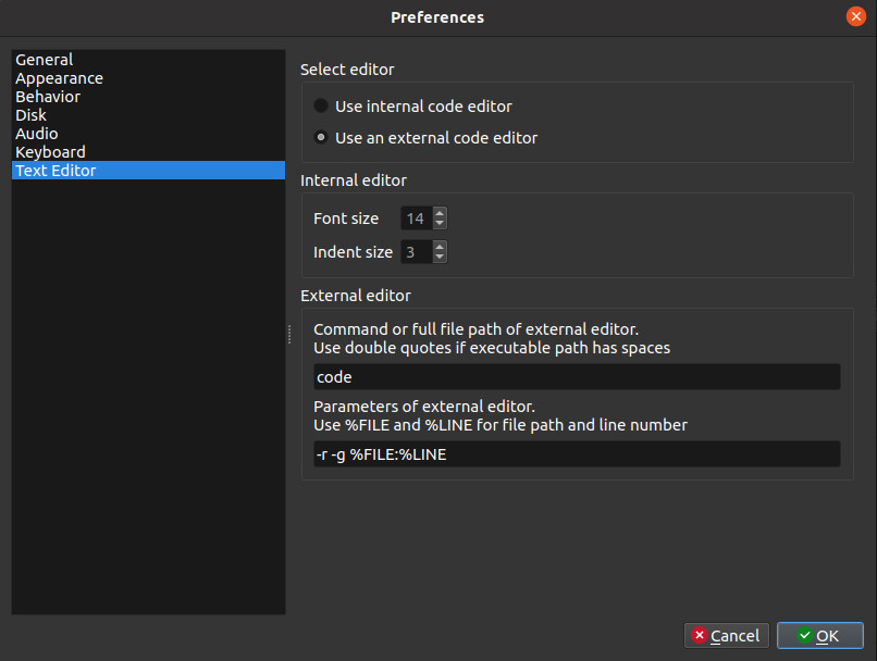
When you select external editor, you have to fill two lines. The first is the executable of the external editor. On unix-like system, just type the command of the editor without arguments, (ex. subl for Sublime or code for VS-code). On Windows you must write the full path of the executable, unless it's located in a folder listed in PATH environment variable. If the path contains white spaces, please enclose it in double quotes.
The second line is the list of arguments that the editor requires to open a specific file. You must replace the path of the file to be edited by %FILE and the line number (if applicable) with %LINE.
With this settings, when you click the beam button for a shader code, a temporary file is created and the external editor is launched with this file. Whenever this file is saved, Olive updates the inputs of the node according to the shader code.
The temporary file is deleted as soon as Olive quits or when the node is deleted. If your external editor detects that the file does not exist anymore, don't try to save it again with the same name: the link with Olive is broken. Instead, return to Olive and click the edit button again.
If your editor does not have a specific highlight for GLSL language, the one for C/C++ will be decent.
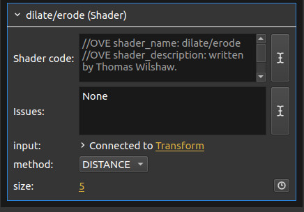
Consider the code in this link, that implements a shader that dilates or erodes a mask as proposed by Thomas Wilshaw:
This shader is (or will soon be) built-in in Olive, but suppose you want to make it your own, (for example to make some tweaks). One of the input is a "method", that is a value that can be selected from a set of finite values. Here's the snippet of the code:
//OVE name: method
//OVE type: SELECTION
//OVE flag: NOT_KEYFRAMABLE, NOT_CONNECTABLE
//OVE values: "BOX", "DISTANCE"
//OVE values: "GAUSSIAN"
//OVE default: 1
//OVE description: algorithm used for process
uniform int method_in;
This uniform has type int, but the //OVE type is SELECTION. This means that the GUI will show a combo box, (or drop-down menu), with the labels listed in values.
Values must be enclosed in double quotes. Each value can internally have spaces but not double quotes (there is no escape character to use double quotes internally). Values can be separated by comma or by spaces, (actually, also by anithing else); they can be listed all in the same line or in different lines: in any case, they are numbered from 0 and keep growing as they are found in the same or in another line.
When you define the default value, use an integer in range 0 to number of items minus one.
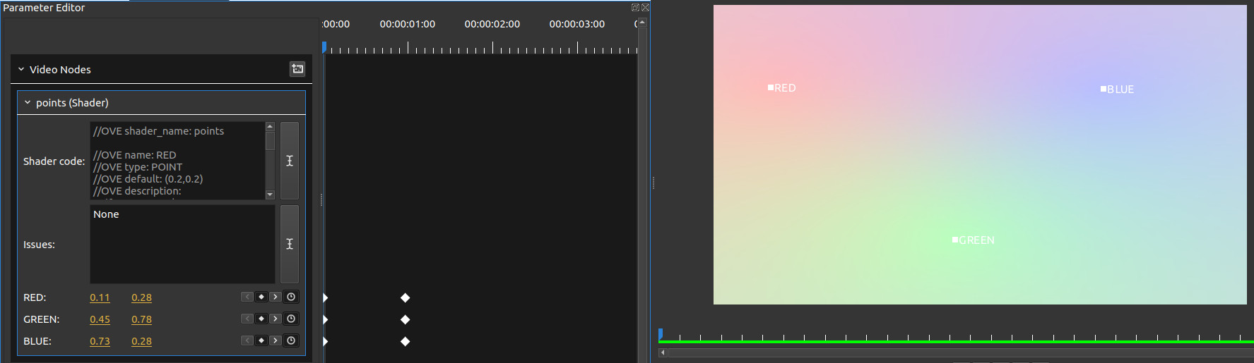
In this example we will define three points in the screen, named RED, GREEN and BLUE. The following node:
uses the distance function to evaluate the distance of each point in the screen from each of the three main point. The value of output red, green and blue values for each point is related to the distance from the main points. You can also animate the position of the poins by the spin boxes in the parameter editor (not very convenient), or by directly dragging with the mouse in the output preview window. The points can also go off-screen.
The coordinates of the points are normalized by the resolution, this means that (0,0) is the top-left of the frame and (1,1) is the bottom-right.
Currently, the type POINT does not support 'min' and 'max' attributes.
This is an example of the output:
Suppose you want a simple brightness/contrast filter and you don't find it in Olive. You don't want to reinvent the wheel so you google for "glsl brightness contrast shader" and one of the first results is from www.shadertoy.com. ShaderToy is a very useful site where you can test your shaders within the web browser. We will now discuss how to port shaders into Olive. In this link we find the following code:
mat4 brightnessMatrix( float brightness )
{
    return mat4( 1, 0, 0, 0,
                 0, 1, 0, 0,
                 0, 0, 1, 0,
                 brightness, brightness, brightness, 1 );
}

mat4 contrastMatrix( float contrast )
{
   float t = ( 1.0 - contrast ) / 2.0;

    return mat4( contrast, 0, 0, 0,
                 0, contrast, 0, 0,
                 0, 0, contrast, 0,
                 t, t, t, 1 );

}

mat4 saturationMatrix( float saturation )
{
    vec3 luminance = vec3( 0.3086, 0.6094, 0.0820 );

    float oneMinusSat = 1.0 - saturation;

    vec3 red = vec3( luminance.x * oneMinusSat );
    red+= vec3( saturation, 0, 0 );

    vec3 green = vec3( luminance.y * oneMinusSat );
    green += vec3( 0, saturation, 0 );

    vec3 blue = vec3( luminance.z * oneMinusSat );
    blue += vec3( 0, 0, saturation );

    return mat4( red,     0,
                 green,   0,
                 blue,    0,
                 0, 0, 0, 1 );
}

const float brightness = 0.55;
const float contrast = 1.8;
const float saturation = 3.5;

void mainImage( out vec4 fragColor, in vec2 fragCoord )
{
    vec4 color = texture( iChannel0, fragCoord/iResolution.xy );

   fragColor = brightnessMatrix( brightness ) *
            contrastMatrix( contrast ) *
            saturationMatrix( saturation ) *
            color;
}
The first thing to do is to add a name to the filter and to give a description that references the source: stealing is fine, but steal honestly.
//OVE shader_name: Brightness/Contrast
//OVE shader_description: taken from https://www.shadertoy.com/view/XdcXzn
The first functions can be used as they are: they define the matrices that implement Brightness, Contrast and Saturation adjustment. Then we find:
const float brightness = 0.55;
const float contrast = 1.8;
const float saturation = 3.5;
These are the settings that are applied to the filter: we want to expose these values as inputs. They are float values but it's not quite clear what are the valid ranges for each one. We must turn them into uniforms, and uniforms can not be assigned with a value. However we can use the proposed values as default.
//OVE name: brightness
//OVE type: FLOAT
//OVE flag: NOT_CONNECTABLE
//OVE min: 0.0
//OVE max: 10.0
//OVE default: 0.55
//OVE description:
uniform float brightness;

//OVE name: contrast
//OVE type: FLOAT
//OVE flag: NOT_CONNECTABLE
//OVE min: 0.0
//OVE max: 10.0
//OVE default: 1.8
//OVE description:
uniform float contrast;

//OVE name: saturation
//OVE type: FLOAT
//OVE flag: NOT_CONNECTABLE
//OVE min: 0.0
//OVE max: 10.0
//OVE default: 3.5
//OVE description:
uniform float saturation;
Then we find this line:
void mainImage( out vec4 fragColor, in vec2 fragCoord )In ShaderToy the main function is not directly visible, but such main function calls this mainImage that has the fragment coordinates as input and the final fragment color as output parameter.
Clearly, in our main function, we have to transform fragColor into the global variable frag_color, while input parameter fragCoord must be mapped to Olive's varyng type ove_texcoord. Note that fragColor in ShaderToy holds the screen coordinates, (eg. [0-1920]x[0-1080]), while Olive's ove_texcoord are normalized in range [0..1]x[0..1]. For this reason there is no need to divide by the resolution, and line:
vec4 color = texture( iChannel0, fragCoord/iResolution.xy );becomes
vec4 composite = texture2D( iChannel0, ove_texcoord);In ShaderToy, the input images (or videos) are named iChannel-n, where n goes from 0 to 3. We will make it in input of type TEXTURE:
//OVE name: input
//OVE type: TEXTURE
//OVE flag: NOT_KEYFRAMABLE
//OVE description:
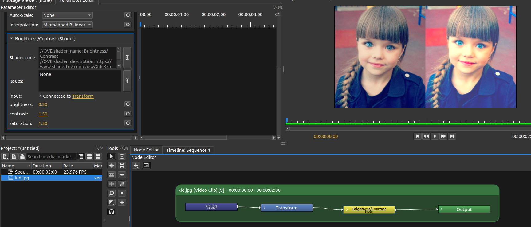
uniform sampler2D iChannel0;You can download the final node here:
Here is an example of output (the image on the right):
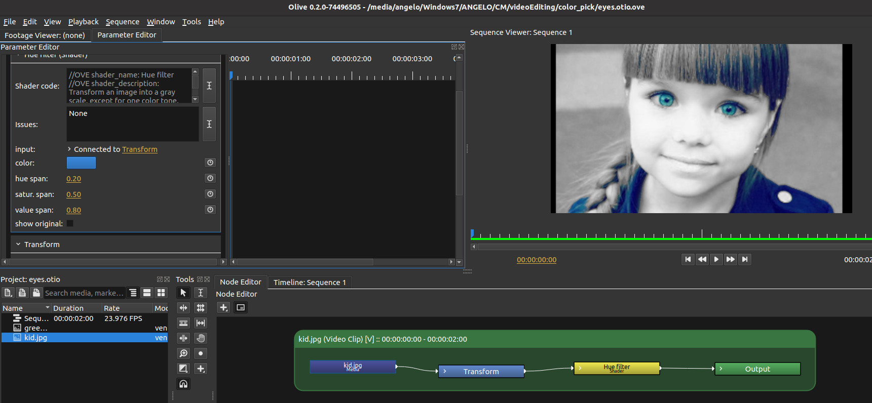
In this example we will show how to pass from an RGB color space to an HSV color space. The shader in this node:
has a color input that indicates a hue to be preserved, while all other values of hue are converted to gray scale. This works mainly with a high saturated color. Then you can select the tolerance in terms of hue, saturation and value.
Internally we have two functions that transform a color from RGB space into HSV space and vice versa.
This is an example of output:
Here we come to the second way to use GLSL shaders: transitions. If we have two strips and we apply a GLSL transition:
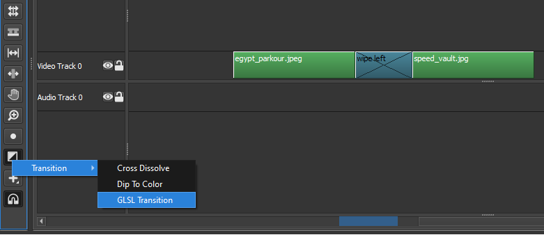
we find a zone between the strips with a blue color. If we click on that zone, in the "Parameter Editor" panel, we find the usual "Shader code" text box that opens a GLSL editor.
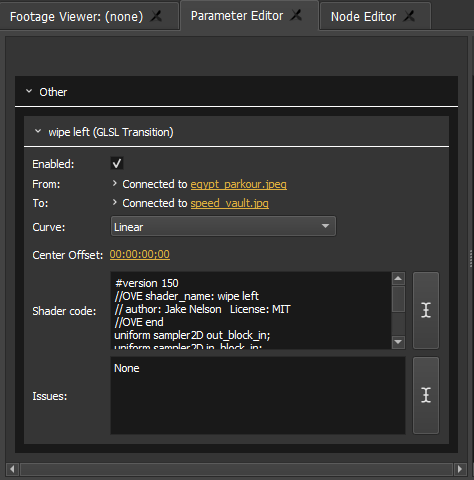
The default transition looks like this:
#version 150
//OVE shader_name: transition
//OVE shader_description:
//OVE end
uniform sampler2D out_block_in;
uniform sampler2D in_block_in;
uniform bool out_block_in_enabled;
uniform bool in_block_in_enabled;
uniform int curve_in;

uniform float ove_tprog_all;

in vec2 ove_texcoord;
out vec4 frag_color;

void main(void) {
    frag_color = texture(in_block_in, ove_texcoord*step( 1.0 - ove_tprog_all, ove_texcoord.xy)) +
                 texture(out_block_in, ove_texcoord*step( ove_tprog_all, ove_texcoord.xy));
}
We still have to remember to use different "shader_name" for instances with different code.
There are no default user inputs, but you can add as many as you want with the same syntax of the filter node. The clips between which the transition occurs are in_block_in and out_block_in. There is also a uniform curve_in input that is not used by default: this defines the transition curve and it is driven by the combo box Curve that can be linear, exponential or logarithmic. We will see how to use this input in the examples below.
The last uniform that we find is uniform float ove_tprog_all. This ranges from 1 to 0 throughout the transition: it is 1 in the first frame and 0 in the last.
The point of the shader is again to give a value to frag_color, based on the two clips and the progress of the transition.
Let us analize a simple transitions that uses the curves provided by the parameter panel. The transition is ported from gl-transitions.com
#version 150
//OVE shader_name: Cross Warp
//OVE shader_description:
// Author: Eke Péter <[email protected]>
// License: MIT

//OVE end

#define LINEAR_CURVE 0
#define EXPONENTIAL_CURVE 1
#define LOGARITHMIC_CURVE 2

uniform sampler2D out_block_in;
uniform sampler2D in_block_in;
uniform bool out_block_in_enabled;
uniform bool in_block_in_enabled;
uniform int curve_in;

/* animated from 0 to 1 */
uniform float ove_tprog_all;

in vec2 ove_texcoord;
out vec4 frag_color;

vec4 getFromColor( vec2 p)
{
  return texture( in_block_in, p);
}

vec4 getToColor( vec2 p)
{
  return texture( out_block_in, p);
}

float TransformCurve(float linear) {
  if (curve_in == EXPONENTIAL_CURVE) {
    return linear * linear;
  } else if (curve_in == LOGARITHMIC_CURVE) {
    return sqrt(linear);
  } else {
    return linear;
  }
}


vec4 transition(vec2 p, float progress) {
  float x = progress;
  x=smoothstep(.0,1.0,(x*2.0+p.x-1.0));
  return mix(getFromColor((p-.5)*(1.-x)+.5), getToColor((p-.5)*x+.5), x);
}


void main(void) {
    frag_color = transition( ove_texcoord.xy, TransformCurve(1.0 - ove_tprog_all));
}
The uniform curve_in is used in function TransformCurve in order to modify the progress passed to transition function, that is the core of the algorithm.
The definitions LINEAR_CURVE, EXPONENTIAL_CURVE and LOGARITHMIC_CURVE are fixed; they are related to the inputs in the combo box of the UI.
The following transitions can generate a result similar to this video. This is a collection of transitions ported from GLSL Transitions site. The credits for each transition are inside the project. In the following links you will find the GLSL code to paste in the transition that you have to create as any other transition in Olive (the menu beside the timeline).
If you download the demo project, you can find more filters implemeted as Shader nodes. They are mainly a port of Olive 0.1 video filters to OpenGL 3.2. Here is a list:
- brigthness/constrast
- bulge
- chromatic aberration
- color correction
- color filter
- colorize node
- crop
- cross stich
- despill unfa
- despill wilshaw
- dilate erode
- directional blur
- emboss
- fish eye
- flip
- gaussian blur
- green screen
- hue mask
- hue/saturation/brightness
- invert
- luma key
- noise
- pixelate
- points
- posterize
- radial blur
- ripple
- sphere
- swirl
- tile
- toonify
- vignette
- wave
Some other shaders, not present in demo project but present in Olive 0.1 as "community maintained", are:
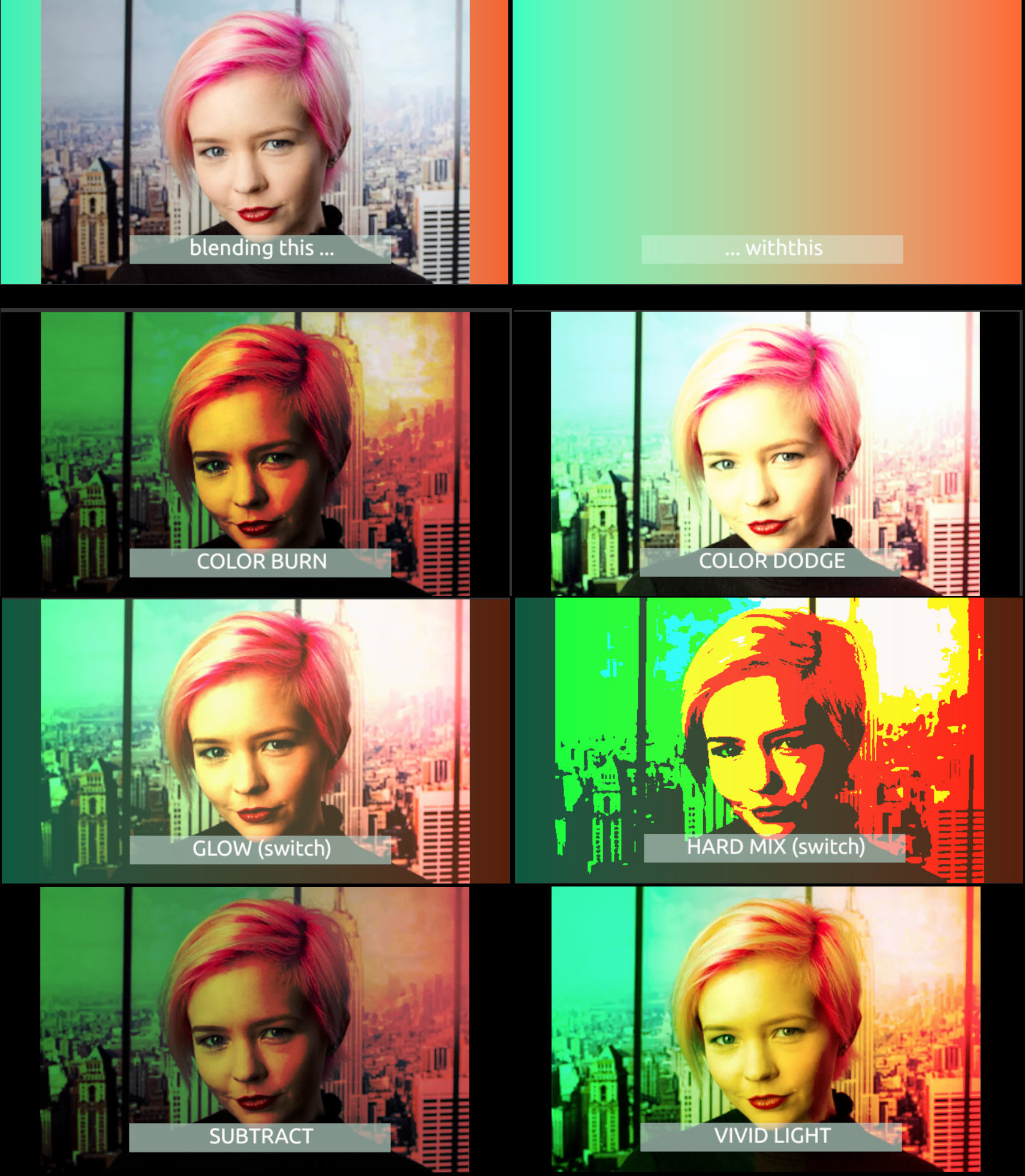
The blend mode demo project shows how blend modes can be implemented with the Shader filter. All blend modes are taken from https://github.com/jamieowen/glsl-blend . You can also download the node setup to include in your projects.
The blending modes that are implemented are:
- ADD
- AVERAGE
- COLOR BURN
- COLOR DODGE
- DARKEN
- DIFFERENCE
- EXCLUSION
- GLOW
- HARD LIGHT
- HARD MIX
- LIGHTEN
- LINEAR BURN
- LINEAR DODGE
- LINEAR LIGHT
- MULTIPLY
- NEGATION
- NORMAL
- OVERLAY
- PHOENIX
- PIN LIGHT
- REFLECT
- SCREEN
- SOFT LIGHT
- SUBSTRACT
- SUBTRACT
- VIVID LIGHT
Here is a sample of outputs for some blending modes; the full result is shown in this video.
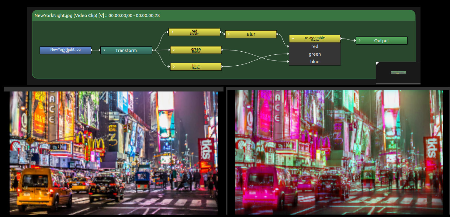
So far, a Shader node has only a single output. If we need more output, such as separated red, green and blue channels, we need to send the same input to several nodes; each node produces one output.
In this example, we separate the channels, then we blur the red channel only, and finally swap green and blue channels. To recombine the channels after processing, a single node is enough. In the final node, it would be easy to control the gain of each channel, so that we can build a channel mixer.