ATMEGA328P
https://www.flickr.com/photos/funnypolynomial/sets/72157627320381707/
The Arduino has a glitch in the alignment of the digital pins -- there's an odd gap between the two sets of 8 sockets which means a strip of pins at the standard 0.1" pitch won't fit. When I discovered this I thought I had a bad board, but it is a known and documented issue (see the bottom of arduino.cc/en/Main/ArduinoBoardUno). But I had my perf board and headers, and really wanted to make my own "shield." I came up with a simple workaround which uses in-line and right-angle headers in tandem to re-create the gap in a way that makes it possible to use standard 0.1" pitch perf board and mate it with an Arduino.

https://wiki.keyestudio.com/Ks0183_keyestudio_Multi-purpose_Shield_V1
Multi-purpose Shield V1 is a learning board based on Arduino. No need for soldering and connection.Download the program to complete experiment. It is multi-purpose and we offer code libraries of all modules that have been tested. You can use them directly. There are extension ports on the shield to help you to complete other experiments.
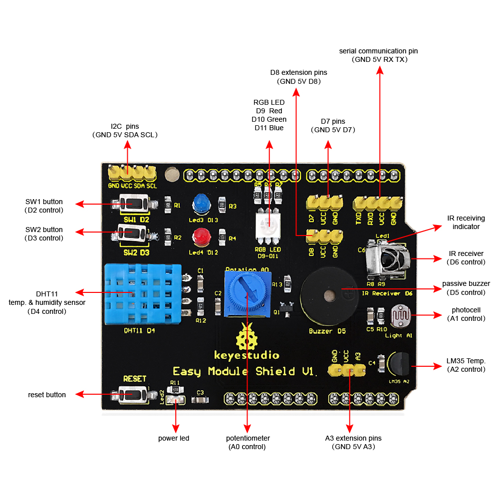
| Arduino | ESPduino-32 | Multifunction Shield |
|---|---|---|
| D02 | 26 | SW1 |
| D03 | 25 | SW2 |
| D04 | 17 | DHT11 |
| D05 | 16 | Buzzer |
| D06 | 27 | IR Receiver |
| D07 | 14 | Header |
| D08 | 12 | Header |
| D09 | 13 | RGB Red |
| D10 | 05 | RGB Blue |
| D11 | 23 | RGB Green |
| D12 | 19 | LED Red |
| D13 | 18 | LED Blue |
| A0 | 02 | Potentiometer |
| A1 | 04 | LDR |
| A2 | 35 | LM35 |
| A3 | 34 | Header |
| A4 | 36 | SDA |
| A5 | 39 | SCL |
Get it from AliExpress https://psqd.pw/arduino-esp8266

Similar to the Arduino Wifi Rev 1 https://www.arduino.cc/en/Guide/ArduinoUnoWiFi
Also see https://github.com/arduino-libraries/UnoWiFi-FirmwareUpdater-Plugin or https://www.arduino.cc/en/Guide/ArduinoUnoWiFiChangeFw for a possible way to update the ESP8266 portion and work with the Arduino through OTA programming.
- sales page: https://robotdyn.com/uno-wifi-r3-atmega328p-esp8266-32mb-flash-usb-ttl-ch340g-micro-usb.html
- schematics: https://github.com/parasquid/mcu-iot-sensors/files/3732217/Schematic.0G-00005215.UNO%2BWiFi-R3-AT328-ESP8266-CH340G.pdf
There seems to be a clone of the RobotDyn version floating around, which is looks mostly the same but doesn't seem to properly connect the DTR signal of the serial chip to the ATMEGA328P's reset pin.
The cloned version would be unable to flash the Arduino portion of the board, even with the correct dip switch settings. You can still flash the Arduino via the ICSP though. Make sure you buy from the original robotdyn store; I bought mine from aliexpress https://psqd.pw/arduino-esp8266
There's a short tutorial on how to flash the (clone) device on youtube: https://www.youtube.com/watch?v=CpN0QNfF4Og which requires you to press the reset button just before uploading (simulating the USB to Serial momentarily pulling DTR to low).
I haven't been fully able to get the timing correct, but just pressing reset over and over until it flashes seems to work.
Here are some pictures of the difference between the original RobotDyn board (which there are no problems with flashing Arduino) and the clone (the RobotDyn is on the left, and the clone is on the right):

The clone board has no markings, unlike the RobotDyn board

They look almost exactly the same on the front side
