Clock
In the freeDSP ALLinONE we used an Abracon ASV-24.576MHZ-E-T clock oscillator with a frequency of 24,576MHz. To distribute the clock to all ICs, we used an IDT 2309NZ clock buffer, that features 9 outputs.
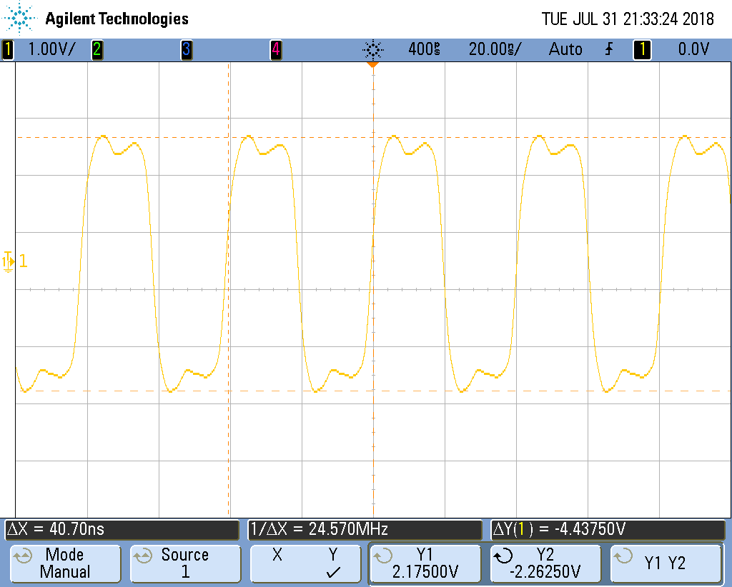
The oscillator provides a rectangular clock signal, which is transformed by the probe we used. Unfortunately, we could not measure two clock signals at the same time, because the probes were interfering each other.
The first diagram shows that the MCLK signal coming from the Abracon is a rectangular signal with higher frequencies visible. This signal was measured at P22.
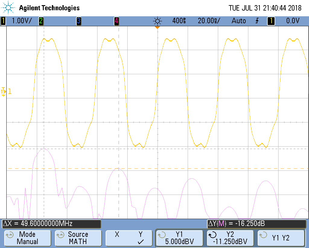
The next diagram shows the FFT of the MCLK together with the signal itself. The first side lobe is at approximately 75MHz (3x MCLK), but it is attenuated by 16dB.
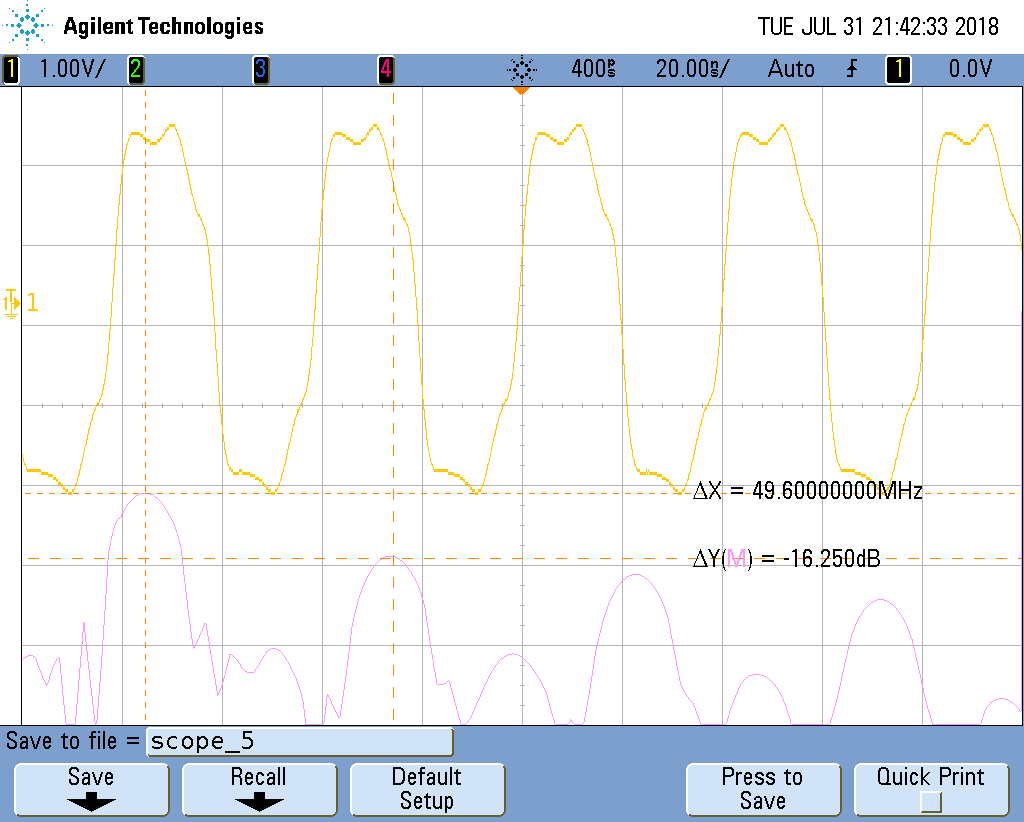
The clock buffer does not change the waveform of the clock signal. This signal was taken at P30.
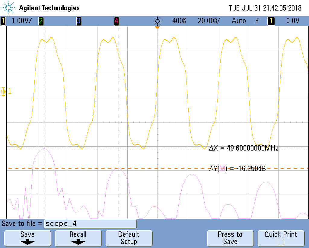
We also measured the clock at each IC on the board, but all signals looked like the following at the MCLK input of the ADAU1701 (Pin 32). This signal was taken at P16.