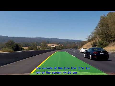
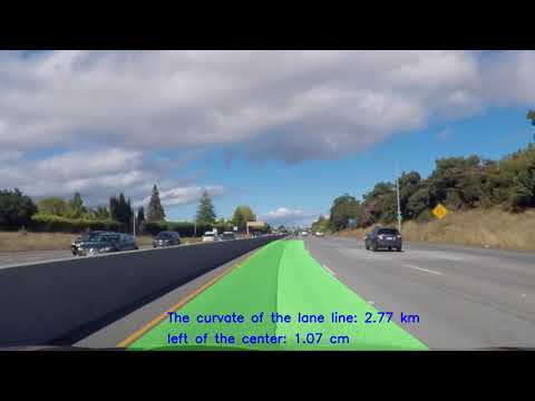
Click the pictures to see the final result of the videos.
Advanced Lane Finding Project
The goals / steps of this project are the following:
- Compute the camera calibration matrix and distortion coefficients given a set of chessboard images.
- Apply a distortion correction to raw images.
- Use color transforms, gradients, etc., to create a thresholded binary image.
- Apply a perspective transform to rectify binary image ("birds-eye view").
- Detect lane pixels and fit to find the lane boundary.
- Determine the curvature of the lane and vehicle position with respect to center.
- Warp the detected lane boundaries back onto the original image.
- Output visual display of the lane boundaries and numerical estimation of lane curvature and vehicle position.
Rubric Points
Here I will consider the rubric points individually and describe how I addressed each point in my implementation.
The code for this step is contained in the first three code cells of the IPython notebook located in "./Advanced_Lane_Lines.ipynb".
I start by preparing "object points", which will be the (x, y, z) coordinates of the chessboard corners in the world. Here I am assuming the chessboard is fixed on the (x, y) plane at z=0, such that the object points are the same for each calibration image. Thus, objp is just a replicated array of coordinates, and obj_points will be appended with a copy of it every time I successfully detect all chessboard corners in a test image. img_points will be appended with the (x, y) pixel position of each of the corners in the image plane with each successful chessboard detection.
I then used the output obj_points and img_points to compute the camera calibration and distortion coefficients using the cv2.calibrateCamera() function. I applied this distortion correction to the test image using the cv2.undistort() function and obtained this result:

To demonstrate this step, I will describe how I apply the distortion correction to one of the test images like this one:

I first used a combination of color and gradient thresholds to generate a binary image, but later when I faced the challange video I found that there were too much noise by using the gray scale. SO I finally use the HLS channel only(thresholding steps at the third part of the code in "./Advanced_Lane_Lines.ipynb".). Here's an example of my output for this step.

The code for my perspective transform includes a function called wrap(), which appears in the 2rd Part of the IPython notebook). The wrap() function takes as inputs an image (img). I chose the hardcode the source and destination points in the picture of the straight line so that the straight lines will look roughly straight and easy for checking.
This resulted in the following source and destination points:
| Source | Destination |
|---|---|
| 190, 720 | 240, 720 |
| 586, 455 | 240, 0 |
| 696, 455 | 1040, 0 |
| 1130, 720 | 1040, 720 |
I verified that my perspective transform was working as expected by drawing the src and dst points onto a test image and its warped counterpart to verify that the lines appear parallel in the warped image.

4. Find the lane lines and polyfit it by sliding the windows and further precious finding around detected lines.
Then I did some other stuff and fit my lane lines with a 2nd order polynomial kinda like this:
- with sliding windows:

- with precious finding around detected lines:

THe relevant code is at the 5th part of the IPython notebook.
I did this in the 6th part of the IPython notebook.
I implemented this step in the 7th part of the IPython notebook. Here is an example of my result on a test image:

Cause I met some problems the first time when I finished the project on challange video, so I used another IPython notebook named "./process_video.ipynb" to solve the problem, and this is also the file, which I found that the gray scale method is not helpful and decided to use the three HLS channels.
In this IPython notebook, I picked the frames, which bad result appeared out and tried to fixed my parameters on them. So if you want to see the final method I got, please open process_video.ipynb.
You can see the video result on the top of this page or click this link to my project video result and this link to my challange video result.
Here I'll talk about the approach I took, what techniques I used, what worked and why, where the pipeline might fail and how I might improve it if I were going to pursue this project further.
To finish this projcet, I used the following techniques:
- Camera calibration.
- Bird-eye view transformation.
- HLS channel with threshold method.
- Find the lane lines with sliding window and on the foundation of the previous lane lines.
The problems I met:
- The pipline are still not stable or just returns bad results under strong sunlight.
- The lane line which is yellow are much more difficult to locate.